It is not only a fully functional graph visualization library, but also an explorer of data relationships.
!!!###!!!title=Force Layout——VisActor/VGraph tutorial documents!!!###!!!!!!###!!!description=Force-directed layout is a common layout algorithm mainly used for undirected graphs (or in directed graphs where the influence of hierarchical relationships on the layout is not a concern). The characteristics of force-directed layout are: simple and intuitive principles, easy implementation, and strong customization capabilities. It is often used to display the relationships of node connections and can be used for analysis of relationship networks, knowledge graphs, and relationship graphs.This algorithm has built-in force functions that are applicable in most scenarios. Generally, you only need to use it as follows:```javascriptimport { Graph, ForceDirectedLayout } from '@visactor/vgraph';// Recommended usage, configured in Graphconst graph = new Graph({ layout: { type: 'force', options: layoutOptions }});// Second usage, direct instantiationconst graph = new Graph(...);const fdp = new ForceDirectedLayout({ // Specify the data involved in the layout graph, ...layoutOptions});graph.set('layout', fdp);```The following is a comparison of the layout effects of vgraph and d3 with default configurations:| vGraph Effect | D3 Effect || --- | --- || <img src="/vgraph/guide/api/vis-by-vgraph.png" width="400"> | <img src="/vgraph/guide/api/vis-by-d3.png" width="400"> || <img src="/vgraph/guide/api/mis-by-vgraph.png" width="400"> | <img src="/vgraph/guide/api/mis-by-d3.png" width="400"> |!!!###!!!
Force-Directed Layout
Force-directed layout is a common layout algorithm mainly used for undirected graphs (or in directed graphs where the influence of hierarchical relationships on the layout is not a concern). The characteristics of force-directed layout are: simple and intuitive principles, easy implementation, and strong customization capabilities. It is often used to display the relationships of node connections and can be used for analysis of relationship networks, knowledge graphs, and relationship graphs.
This algorithm has built-in force functions that are applicable in most scenarios. Generally, you only need to use it as follows:
import { Graph, ForceDirectedLayout } from'@visactor/vgraph';
// Recommended usage, configured in Graphconst graph = new Graph({
layout: {
type: 'force',
options: layoutOptions
}
});
// Second usage, direct instantiationconst graph = new Graph(...);
const fdp = new ForceDirectedLayout({
// Specify the data involved in the layout graph,
...layoutOptions
});
graph.set('layout', fdp);
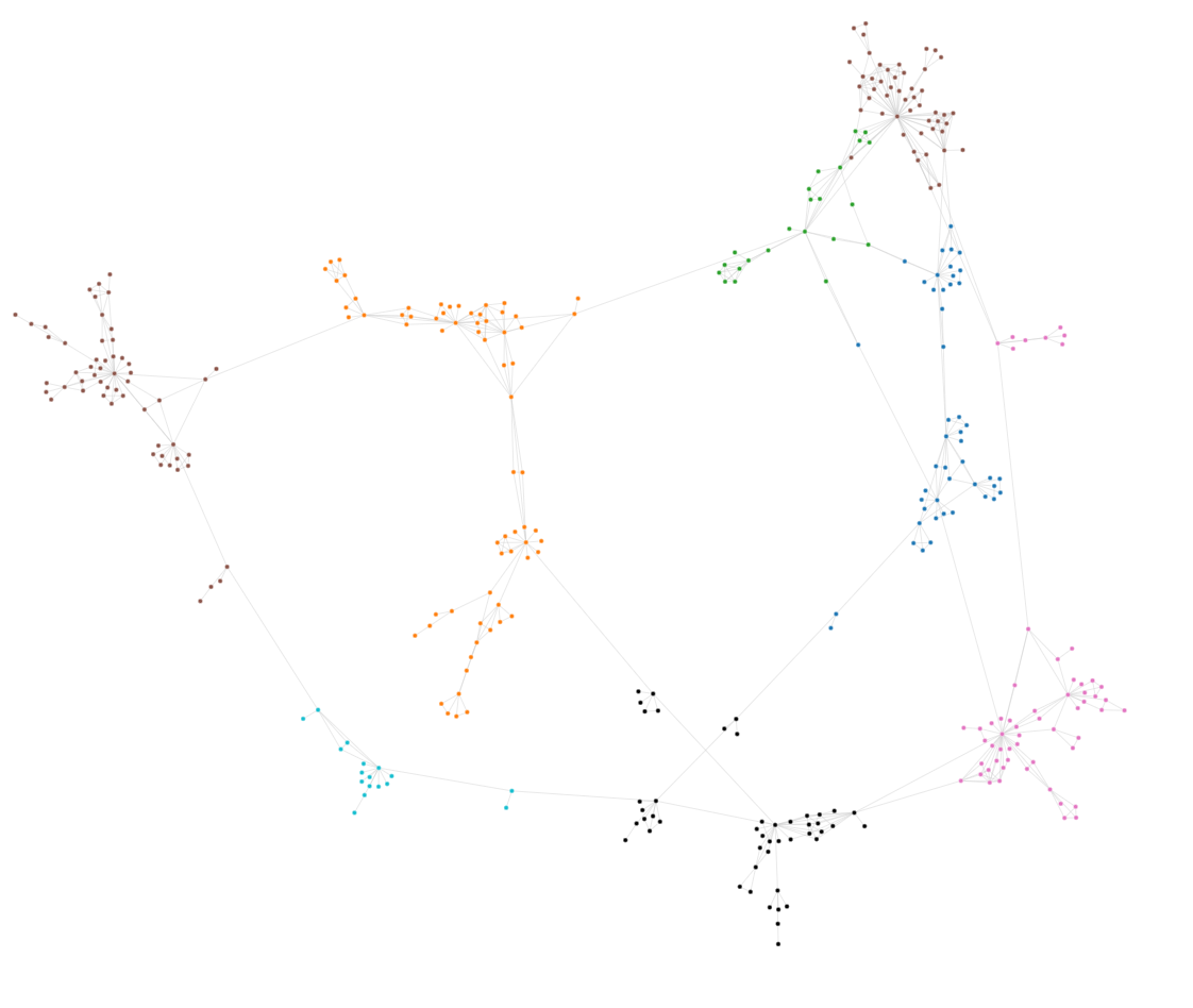
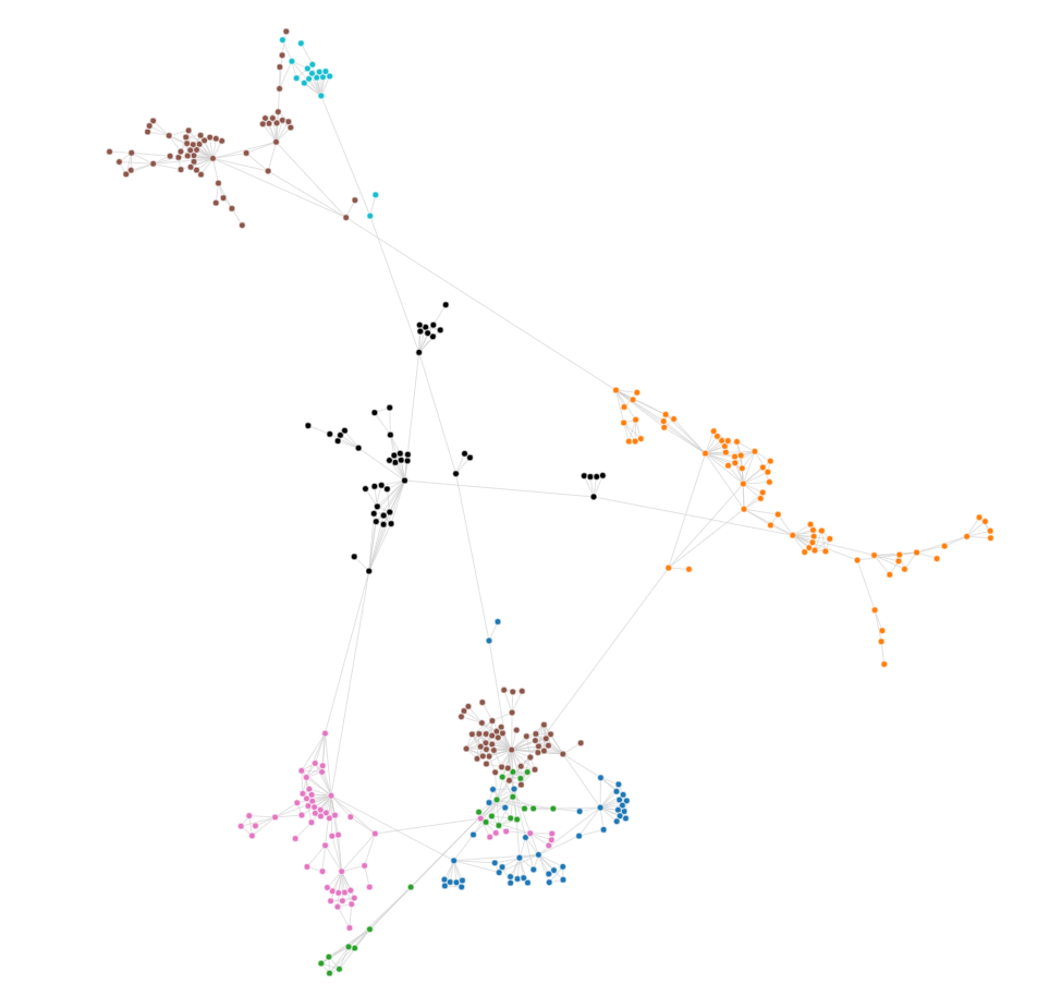
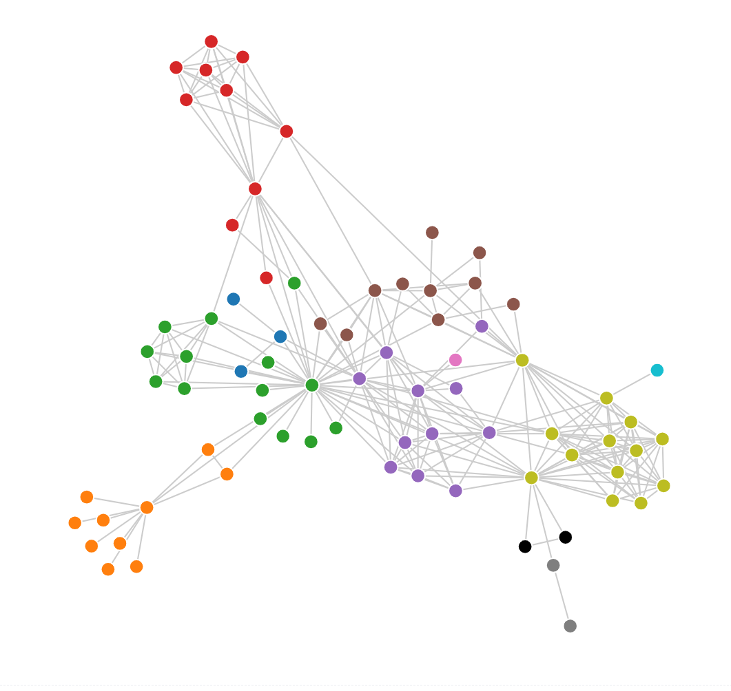
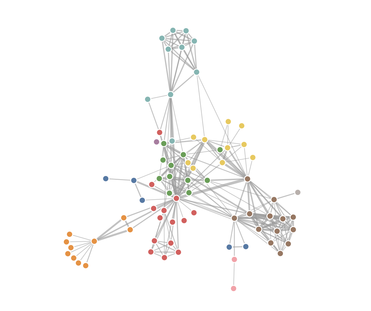
The following is a comparison of the layout effects of vgraph and d3 with default configurations:
vGraph Effect
D3 Effect
Configuration Options
Field
Data Type
Description
data
{nodes:any[], edges?:any[]}
[Required] Sets the data to be laid out. nodes are required, edges are optional. If data is not configured, other parameters can be configured first, and the data can be set later through the setData interface.
forces
{ [key: string]: ForceBase }
Custom applied force functions. If not set, the default configuration is used. You can add, delete, modify, and query through Force Function Instance Methods.
maxIteration
number
Specifies the maximum number of iterations.
clearOnEndOnFirstCall
boolean
[NEW] Whether to clear the layout end callback after the first layout ends. This is often used for scenarios where fitView or alignView is needed after the first layout, while subsequent layouts maintain the viewport content.
tickIterations
number
The number of iterations per tick. The default is 1. The larger tickIterations, the fewer the total number of ticks.
initMode
'pivotMDS'| 'spiral' | 'random'
Specifies the initial layout method. The default is 'pivotMDS'.
center
{ x: number, y: number }
Specifies the center of the layout.
onTick
()=>{ }
The callback function to run after each tick. A common usage is to refresh the canvas to achieve an animation effect. It can be modified through setOnTick(fn:()=>{}).
onEnd
()=>{ }
The callback function to run after the layout is complete. A common usage is to pan and zoom the layout to the center of the canvas. It can be modified through setOnEnd(fn:()=>{}).
Instance Methods
Data and Parameters
Instance Method
Return Value
Description
setOptions(options)
void
Sets the options in the table above, such as fdp.setOptions({maxIteration:100}).
Running Status
Instance Method
Return Value
Description
stop()
void
Stops the timer. Iteration also stops.
start()
void
Restarts the timer without making other state changes.
restart()
void
Restarts the operation, resets the iteration count, resets alpha to options.restartAlpha, and restarts the timer.
step()
void
Manually runs an iteration step without calling it through the timer.
Configures and initializes the forces. If no forces are specified, the default forces are used. * This will generate the following call chain: configForces -> initializeForces -> force.initialize(nodes)
initializeForces()
void
Initializes all force functions. Injects node data information into the force functions, and the force functions perform pre-calculation internally.
addForce(key: string, force: ForceBase)
void
Adds a force with the key value key.
removeForce(key: string)
void
Deletes the force with the specified key.
setForce(key: string, options: {})
void
Modifies the parameters of the force with the key value key.
getForces()
forces: Map<key, force>
Returns the force Map of the current state of the FDP instance.
Default Force Functions
The default force functions use the following configuration:
You can copy this configuration into your code and use it to configure the force-directed layout instance, which is convenient for debugging and modifying the force function configuration.
Automatic Configuration of Force Functions
The automatic configuration of force functions method autoFDP is mostly used in scenarios where the scale and characteristics of the displayed data are not known in advance. This method will analyze the data scale and characteristics to recommend a scaling ratio and force configuration. That is:
Attraction force ForceLink
Repulsion force ForceManyBody
Centripetal force ForceCenter
Collision force ForceCollision
The configuration item options is as follows:
Field
Type
Description
nodeSize
number
The node size is required to speed up the calculation. If the node sizes are not uniform, you can enter the average of the sizes.
graphSize
number[]
The size of the graph. The same as the width and height of the graph.
scaleFactor
number
The overlay scaling ratio. The default is 1. If the scaling ratio obtained from your dataset is always too large/small, you can adjust it by overlaying the scaling.
The Web Worker version of the force-directed layout, syncFDP, is used for synchronous layout calculations of large amounts of data in a Web Worker. It is less time-consuming than direct calculation on the page, and the user experience is better.
  const worker = new ForceWorker();
  // data is a generic data structure { nodes: [], edges: [] }
  worker.postMessage({ data, options: ForceOptions });
  worker.onmessage = (event: any) => {
    graph.data(event.data);
    graph.fitView();
  };
The configuration item ForceOptions accepted by syncFDP is as follows:
Field
Type
Description
maxIteration
number
Specifies the maximum number of iterations.
nodeSize
number
The size of the nodes in the graph.
graphSize
number[]
The size of the canvas.
autoForce
boolean
Use the recommended force parameters from the automatic configuration of force functions for the layout.
forces
{ [key: string]: any }
Custom forces and parameters. When autoForce is not enabled and forces are not configured, the layout will be performed using the default force parameters.
Therefore, a simple synchronous force-directed configuration should be referenced as follows:
worker.postMessage({ data, options: {
maxIteration: 150,
// You can enable autoForces to use the automatic configuration of force functions. After enabling, configuring forces will be invalid.// autoForces: true,nodeSize: 15,
graphSize: [800, 600],
forces: {
link: { distance: 30 },
manyBody: { strength: -30 },
collision: { radius: 8 },
center: { x: 400, y: 300 }
},
} });
The correspondence between the key of the forces in the configuration items and the normal configuration of forces is as follows: